What's the Impact of Epoxy Coating Thickness on Breakdown Voltage?
Epoxy powder coatings are a cornerstone of electrical insulation, widely used in transformers, busbars, motors, and other high-voltage components due to their excellent dielectric strength and durability. A critical factor influencing their performance is coating thickness, which directly affects breakdown voltage—the voltage at which an insulating material fails and conducts electricity. This article explores how epoxy coating thickness impacts breakdown voltage, key considerations for selecting the right thickness, and best practices for achieving optimal insulation performance in electrical applications.
Understanding Breakdown Voltage and Epoxy Coatings
Breakdown voltage is the maximum voltage an insulating material can withstand before dielectric failure occurs, leading to arcing, short circuits, or component damage. For epoxy powder coatings, breakdown voltage is closely tied to coating thickness, typically measured in volts per unit thickness (e.g., kV/mm). Epoxy coatings offer dielectric strengths ranging from 10 to 50 kV/mm, making them ideal for applications requiring robust insulation, such as power distribution systems and electronic circuits.
Coating thickness, usually measured in microns (µm) or millimeters (mm), determines how much voltage the coating can handle. Thicker coatings generally provide higher breakdown voltages, but the relationship is not always linear, and other factors like application method, formulation, and environmental conditions play a role.
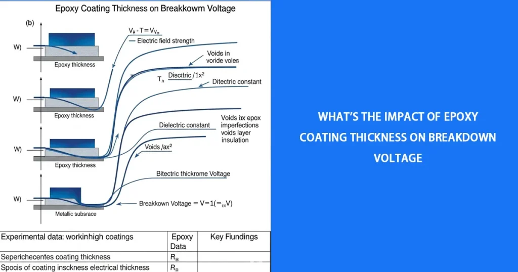
How Coating Thickness Impacts Breakdown Voltage
1. Linear Relationship in Ideal Conditions
In ideal conditions (e.g., uniform coating, no defects, controlled environment), breakdown voltage increases linearly with coating thickness. For example:
- A 200 µm (0.2 mm) epoxy coating with a dielectric strength of 30 kV/mm can withstand 6,000 volts (0.2 mm × 30 kV/mm).
- A 1,000 µm (1 mm) coating with the same dielectric strength can withstand 30,000 volts.
This relationship holds because thicker coatings provide a longer path for electrical current to travel, increasing resistance to breakdown.
Example: SolEpoxy’s DK15-0907 epoxy powder, with a dielectric strength of 30 kV/mm, achieves a breakdown voltage of 15 kV at 500 µm and 36 kV at 1,200 µm in controlled tests.
2. Diminishing Returns at Higher Thicknesses
Beyond a certain thickness (typically 1,500–2,000 µm), the increase in breakdown voltage may slow due to:
- Coating Imperfections: Thicker coatings applied via fluidized bed dipping are prone to voids, bubbles, or uneven curing, which create weak points and reduce effective dielectric strength.
- Thermal Stress: Thick coatings may crack under thermal cycling, especially in high-temperature applications (e.g., motors operating at 155°C), lowering breakdown voltage.
- Material Limitations: The epoxy’s intrinsic dielectric strength caps the maximum achievable breakdown voltage, regardless of thickness.
Key Insight: For high-voltage applications (>38 kV), aim for 1,000–2,000 µm coatings, but ensure proper application to avoid defects.
3. Minimum Thickness Requirements
For low- to medium-voltage applications, thinner coatings (200–500 µm) applied via electrostatic spraying are sufficient. However, below a minimum thickness (e.g., 100 µm), the coating may not provide adequate insulation, leading to premature breakdown. Industry standards like IEC 60243 recommend a minimum thickness of 200 µm for reliable dielectric performance in most applications.
Example: A 100 µm coating with a dielectric strength of 20 kV/mm provides a breakdown voltage of only 2,000 volts, insufficient for medium-voltage busbars requiring 10–15 kV.
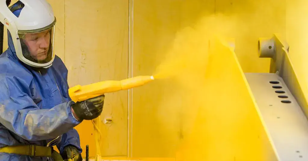
4. Application Method and Thickness Uniformity
The method of applying epoxy powder coating significantly affects thickness and, consequently, breakdown voltage:
- Electrostatic Spraying: Produces thin, uniform coatings (200–500 µm) with consistent dielectric strength, ideal for low- to medium-voltage components like PCBs or motor windings.
- Fluidized Bed Dipping: Achieves thicker coatings (1,000–5,000 µm) for high-voltage applications like busbars, but requires preheating (200–220°C) to ensure uniformity and avoid defects.
Non-uniform thickness (e.g., thin spots or uneven layers) creates weak points where breakdown voltage is lower, increasing the risk of failure. For instance, a 1,000 µm coating with a 200 µm thin spot may fail at the voltage expected for the thinner section.
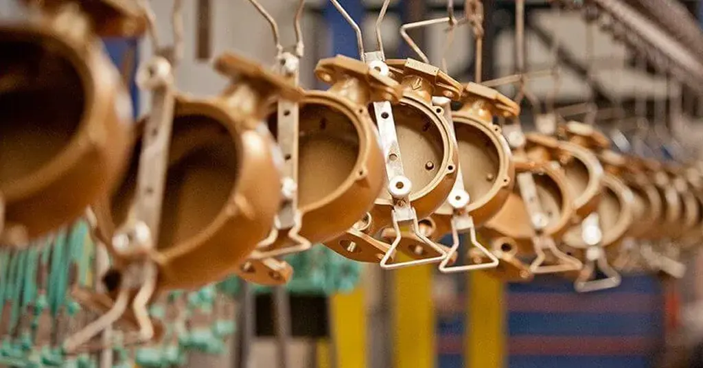
Applications Affected by Coating Thickness
Coating thickness directly impacts breakdown voltage in various applications:
- Transformers: Require 500–1,500 µm coatings to insulate windings against voltages of 10–38 kV, ensuring high breakdown voltage in compact designs.
- Busbars: High-voltage busbars (up to 50 kV) use 1,200–5,000 µm coatings applied via fluidized bed for maximum breakdown voltage.
- Electric Motors: Thin coatings (200–400 µm) suffice for low-voltage motors, while medium-voltage motors need 500–1,000 µm for higher breakdown voltages.
- Capacitors and PCBs: Thin, uniform coatings (100–300 µm) provide sufficient breakdown voltage for low-voltage electronics.
- Aerospace and Automotive: Components like battery housings require 500–1,200 µm coatings to balance breakdown voltage and weight.
Factors Influencing Thickness and Breakdown Voltage
1. Epoxy Formulation
The dielectric strength of the epoxy powder itself determines the baseline breakdown voltage. High-performance formulations (e.g., SolEpoxy DK15-0607, 30 kV/mm) provide higher breakdown voltages than standard powders (15–20 kV/mm). Specialized formulations with enhanced cross-linking or fillers improve performance at thicker layers.
2. Substrate Preparation
Proper surface preparation ensures adhesion and uniform thickness:
- Cleaning: Remove oils, oxides, or contaminants using abrasive blasting or chemical degreasers.
- Primers: Apply corrosion-resistant primers on metals like copper to enhance adhesion and prevent delamination, which could reduce breakdown voltage.
Poor adhesion can lead to peeling or voids, lowering the effective thickness and breakdown voltage.
3. Environmental Conditions
Environmental factors like humidity or temperature can affect coating performance:
- Humidity: Moisture ingress in humid environments (>85% RH) reduces dielectric strength, requiring thicker coatings to maintain breakdown voltage.
- Temperature: High temperatures (e.g., >130°C) may degrade thinner coatings, necessitating thicker layers or high-temperature formulations (Class F/H, up to 180–200°C).
Example: In a tropical climate (90% RH), a 500 µm coating may need to be increased to 800 µm to achieve the same breakdown voltage as in a dry environment.
4. Curing Process
Proper curing at 150–200°C ensures a dense, uniform coating that maximizes breakdown voltage. Under-curing leaves porous structures, while over-curing can cause brittleness, both reducing insulation effectiveness.
Best Practice: Use curing ovens with precise temperature control and verify coating integrity with dielectric strength tests (e.g., per IEC 60243).
Best Practices for Optimizing Coating Thickness
- Determine Voltage Requirements: Calculate the required breakdown voltage based on the application’s maximum operating voltage, adding a 20% safety margin.
- Select Appropriate Thickness: Choose 200–500 µm for low-voltage, 500–1,500 µm for medium-voltage, and 1,200–5,000 µm for high-voltage applications.
- Choose the Right Application Method: Use electrostatic spraying for thin coatings or fluidized bed dipping for thicker layers, ensuring uniformity.
- Ensure Proper Surface Preparation: Clean and dry substrates, using primers if needed, to achieve strong adhesion and consistent thickness.
- Test Breakdown Voltage: Use a dielectric strength tester (e.g., Megger MIT525) to verify the coating’s performance post-application.
- Monitor Environmental Conditions: Apply coatings in controlled environments (RH <60%) and select moisture-resistant formulations for humid conditions.
Comparison of Coating Thickness and Breakdown Voltage
| Thickness (μm) | Breakdown Voltage (kV) | Application Method | Typical Applications |
|---|---|---|---|
| 100–300 | 2–9 (at 30 kV/mm) | Electrostatic Spraying | PCBs, low-voltage motors |
| 300–500 | 9–15 | Electrostatic Spraying | Medium-voltage motors, capacitors |
| 500–1,200 | 15–36 | Fluidized Bed/Spraying | Transformers, busbars (10–38 kV) |
| 1,200–5,000 | 36–150 | Fluidized Bed Dipping | High-voltage busbars (>38 kV) |
| Note: Breakdown voltage assumes a dielectric strength of 30 kV/mm. Actual values vary by formulation and application quality. | |||
Top Epoxy Powder Manufacturers for High Breakdown Voltage
| Manufacturer | Product Line | Dielectric Strength | Max Thickness (μm) | Key Features |
|---|---|---|---|---|
| SolEpoxy | DK15-0907 | 30 kV/mm | 5,000 | High breakdown voltage, thermal stability |
| PPG Coatings | Corvel Series | 25–35 kV/mm | 2,000 | Uniform thickness, moisture resistance |
| CAPLINQ | Hysol DK Series | 20–40 kV/mm | 1,500 | RoHS-compliant, high adhesion |
| ThreeBond | TB Series | 15–30 kV/mm | 1,200 | Easy application, corrosion resistance |
Conclusion
Epoxy coating thickness has a direct and significant impact on breakdown voltage, with thicker coatings providing higher voltage resistance, though subject to diminishing returns and application challenges. By carefully selecting thickness based on voltage requirements, using appropriate application methods, and ensuring proper surface preparation and curing, you can maximize breakdown voltage for reliable electrical insulation. Whether for transformers, busbars, or motors, choosing the right epoxy powder and thickness ensures safety, durability, and performance.

Erik
Doctor of Chemical Engineering, expert in the field of powder coatings, with over 20 years of professional experience in the research and application of powder coatings
Latest news

Have Anything To Ask Us?